-
Products & Solutions TopProducts & Solutions

-
 Products & Solutions Top
-
Drives & Controls
-
UPS & Industrial Power Supply
-
Sensors & Measurements
-
Energy Management
-
Monitoring & Control System
-
Distributions & Controls
-
Transmission & Distribution
-
Transit System
-
Semiconductors
-
Energy
-
Food and Beverage Distribution
-
Service & Equipment Upgrades
-
Solutions
-
-
IR TopInvestor Relations
- GLOBAL > HMI > V10/V9 series > Questions about > How to check the operation of screens without connecting to a PLC
GLOBAL
How to check the operation of screens without connecting to a PLC
How to check the operation of screens without connecting to a PLC
- Category :
Answer
Use the simulator.
The simulator allows you to verify screen operations without a PLC.
The simulator runs on a PC and simulates bit device ON/OFF action and word device data input.
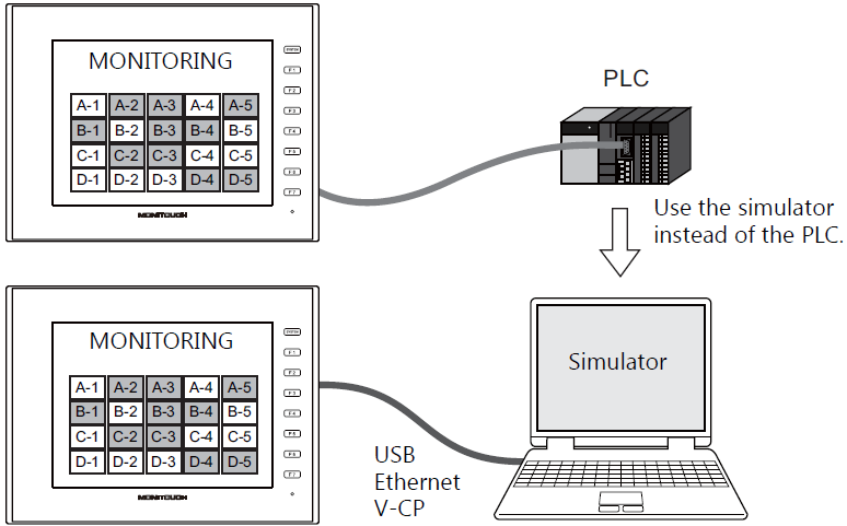
Connection between PC and MONITOUCH
- Serial connection
- USB connection
- Ethernet connection
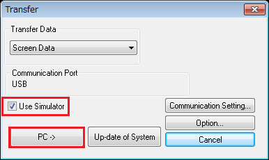
[Transferring screen data]
Click [File] -> [Transfer] -> [Download] on the V-SFT editor to display the [Transfer] dialog.
- Check [Use Simulator] and click the [PC ->] button to transfer the data.
Example: For USB connection
[Settings on the V10/V9 series]
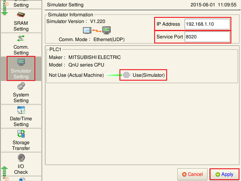
After transferring data, switch to Local mode and display the Simulator Setting screen.
Configure settings on the Simulator Setting screen.
The model names of the logical ports (PLC1 - PLC8) are displayed each with a [Not Use (Actual Machine)]/[Use] selector switch for the simulator.
Select [Use] for devices to operate using the simulator and press [Apply].
For connection via Ethernet (when [Comm. Mode] is set to [Ethernet (UDP)]), also set the IP address of the PC.Example: For USB connection
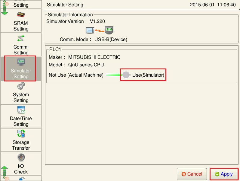
Example: For connection via Ethernet, also set the IP address of the PC.

[Starting the simulator]
Click [Transfer] -> [Simulator] on the V-SFT editor.
The simulator starts up.

The simulator starts communicating as soon as the [Simulator] window opens.
During communication, [Communication] [Start] is checked, and the [Communication] icon is depressed.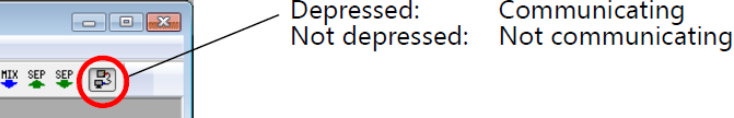
- Double-click on the [Value] cell or click [Change Setting Value] on the right-click menu.
Double-click

- Right-click menu

- The [Write Device] dialog is displayed.
Enter a value and click [OK] to update the value on the [Simulator] window.
The input value is also displayed on the V series.

It is also possible to bit-write by clicking the ON/OFF icons in the [Simulator] window.

When connecting MONITOUCH to a PLC after operations are verified, configure as below. - Select [Not Use (Actual Machine)] on the Simulator Setting screen in Local mode.
or - Click [File] -> [Transfer] -> [Download] on the V-SFT editor, uncheck [Use Simulator] and transfer screen data again.
- Select [Not Use (Actual Machine)] on the Simulator Setting screen in Local mode.
When communication is not successful:
If the simulator's communication settings are not correct, the V series cannot communicate with a PC properly.
If not successful, click [Communication] [End] on the simulator to abort communication. Be sure to select [File] [Communication Setting] and check the settings.
<USB communication>
Select [File] on the simulator and check [Comm. through USB].

<Ethernet communication>
- Register the IP address of the PC on the Simulator Setting screen on MONITOUCH.
- Select [File] on the simulator, check that [Comm. through Ethernet] is checked, and click [Communication Setting].
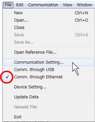
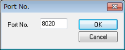
- Set the port number.
The default port No. is 8020.
If changed, set the changed port number on the Simulator Setting screen on MONITOUCH.
<Serial communication>
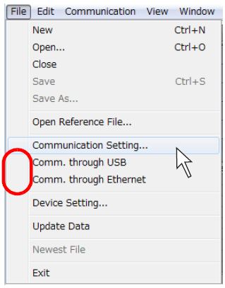
- Select [File] on the simulator, check that [Comm. through USB] and [Comm. through Ethernet] are not checked, and click [Communication Setting].
- Set the COM number for [Communication Port]. Set the same COM number as that on the PC.
