-
Products & Solutions TopProducts & Solutions

-
 Products & Solutions Top
-
Drives & Controls
-
UPS & Industrial Power Supply
-
Sensors & Measurements
-
Energy Management
-
Monitoring & Control System
-
Distributions & Controls
-
Transmission & Distribution
-
Transit System
-
Semiconductors
-
Energy
-
Food and Beverage Distribution
-
Service & Equipment Upgrades
-
Solutions
-
-
IR TopInvestor Relations
- GLOBAL > HMI > V8/TS2060 series > Questions about > How to display overlap parts from the PLC (external)
How to display overlap parts from the PLC (external)
How to display overlap parts from the PLC (external)
- Category :
Answer
There are four overlap part types.
- Normal overlap
- Call-overlap
- Multi overlap
- Global overlap
In the case of external commands, the display method differs.
[Normal/call overlap]
Two methods are available.
<Using the read area>
The overlap part will be displayed when bit 0 to 2 of read area "n + 1" corresponding to the desired overlap ID number is turned ON.
* For details about how to check Read area, click here.
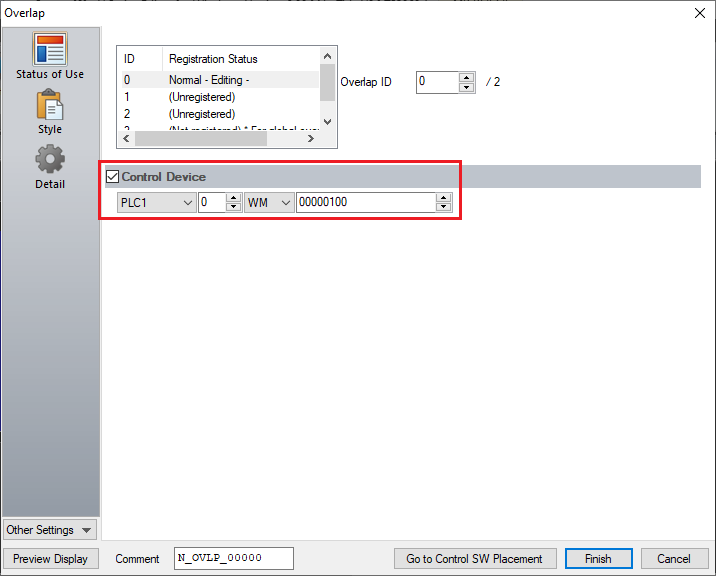
<Using the control device memory>
Check [Control Device] in the [Overlap] dialog on the V-SFT-6 editor.
The overlap part will be displayed when bit 0 of the specified cotrol device memory is turned ON.
Example: Normal overlap
[Multi/Global overlap]
Two methods are available.
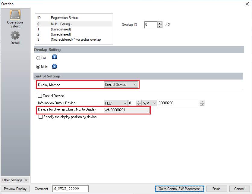
<Using the read area>
Display the [Overlap] dialog or select [System Setting] → [Global Setting] → [Global Overlap Setting], and select [Display Method: Control Device] on the V-SFT-6 editor.
Set the PLC device memory for [Info Output Device].
A device memory address is set for [Device Overlap Library No. to Display] (= information output device "n + 1").
(The overlap library number to be displayed is stored in this device memory address.)
Example: Multi-overlap
Contents of info output deviceDevice Contents Operation n The overlap library number of the multi/global overlap part currently displayed on the screen is stored.
When no overlap display is shown, "-1" is stored.V/TS→PLC n+1 Specify the overlap library number to be displayed. V/TS ← PLC n+2 * Specify the X coordinate of the multi/global overlap display. V/TS ← PLC n+3 * Specify the Y coordinate of the multi/global overlap display. V/TS ← PLC * Valid when the [Specify the display position by device] is checked.
- The overlap part will be displayed when the bit of read area "n + 1" corresponding to the desired overlap ID number is turned ON.
- Multi overlap: Bit 0 to 2 of read area "n + 1"
- Global overlap: Bit 3 of read area "n + 1"

* For details about how to check Read area, click here.
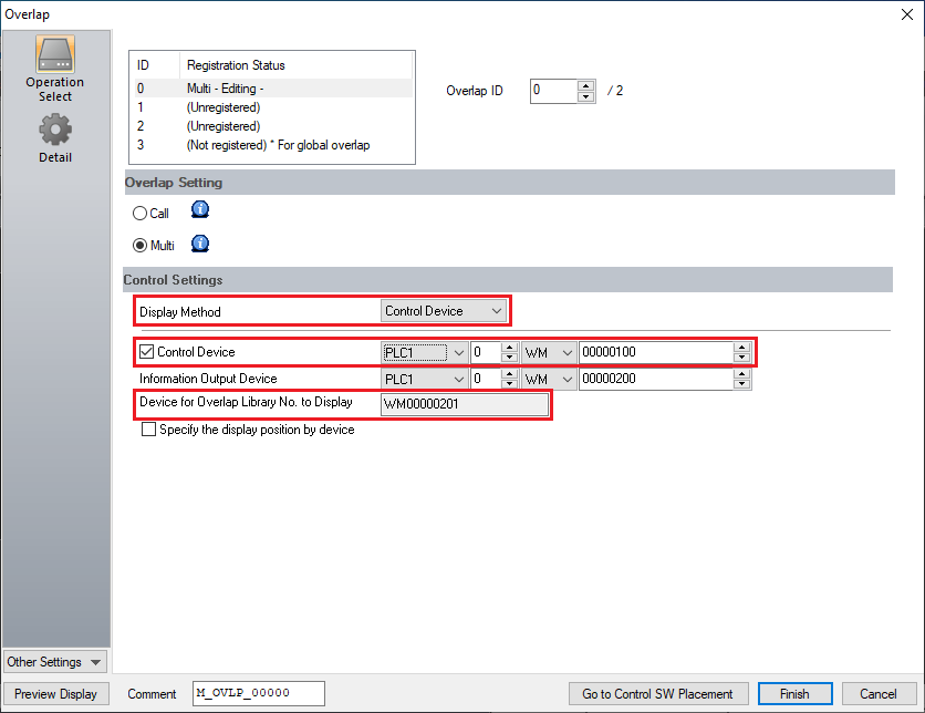
<Using the control device memory>
- Display the [Overlap] dialog or select [System Setting] → [Global Setting] → [Global Overlap Setting], and select [Display Method: Control Device] on the V-SFT-6 editor.
Set the PLC device memory for [Info Output Device]. - Check [Control Device].
- A device memory address is set for [Device Overlap Library No. to Display] (= information output device "n + 1").
(The overlap library number to be displayed is stored in this device memory address.)
Example: Multi-overlap
 * For more information of the Info Output Device, refer to the "Contents of info output device" above.
- The overlap part will be displayed when the number to display is set for [Device Overlap Library No. to Display] set in step (1) and bit 0 of the control device memory is turned ON.